Aircraft

NASA reveals what the final X-57 all-electric X-plane will look like

View 3 Images
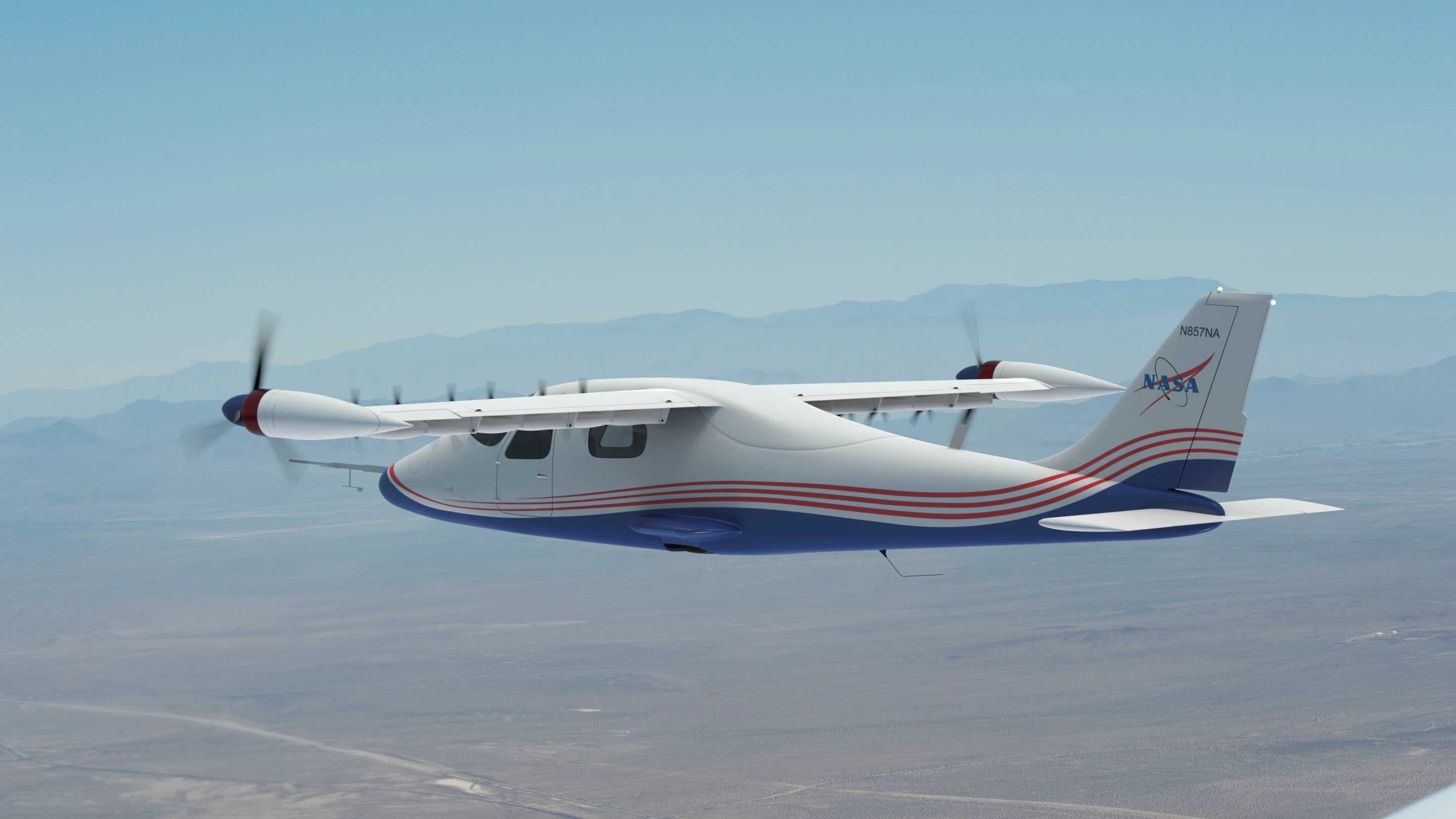
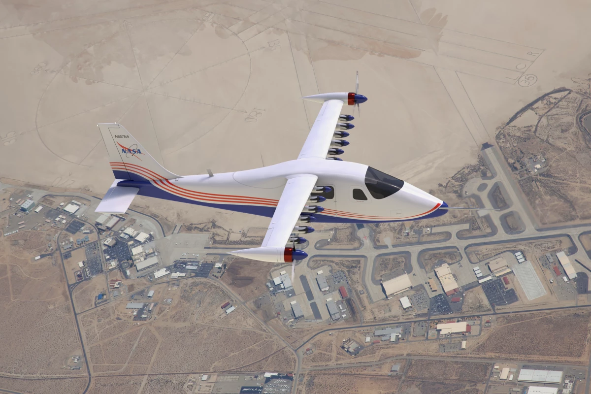
This artist’s concept image shows NASA’s first all-electric X-plane, the X-57 Maxwell, in its final configuration, flying in cruise mode over NASA’s Armstrong Flight Research Center in Edwards, California
NASA Langley/Advanced Concepts Lab, AMA, Inc
This artist’s concept image shows NASA’s first all-electric X-plane, the X-57 Maxwell, in its final configuration, flying in cruise mode over NASA’s Armstrong Flight Research Center in Edwards, California
NASA Langley/Advanced Concepts Lab, AMA, Inc
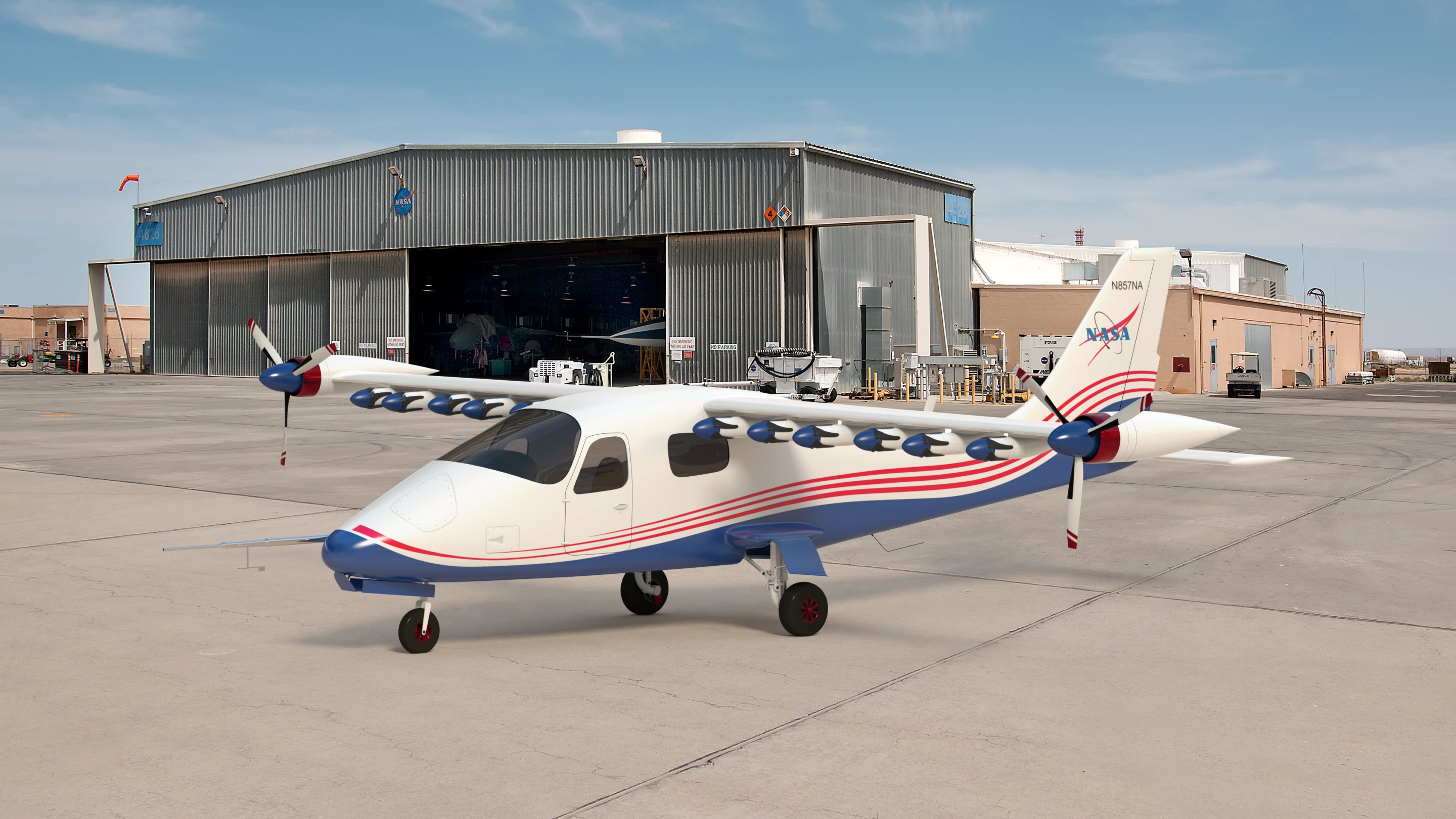
This artist’s concept image shows NASA’s first all-electric X-plane, the X-57 Maxwell, sitting in its final configuration in front of a hangar at NASA’s Armstrong Flight Research Center in Edwards, California
NASA Langley/Advanced Concepts Lab, AMA, Inc
This artist’s concept image shows NASA’s first all-electric X-plane, the X-57 Maxwell, flying shortly after takeoff
NASA Langley/Advanced Concepts Lab, AMA, Inc
View gallery - 3 images

NASA has released three concept art images showing its X-57 Maxwell all-electric X-plane in its final configuration. The first manned X-plane from NASA in two decades, the X-57 is shown in its Modification iV (Mod IV) form, which includes a high-aspect-ratio wing and 5-ft (1.5-m) diameter wingtip propellers to recover energy from wingtip vortices.

Designed to help develop certification standards that can be applied to electric aircraft as they come onto the market, the X-57 began as a four-seater Tecnam P2006T conventional light aircraft that had its twin Rotax 912S3 four-cylinder piston engines replaced by 12 electric motor nacelles with individual propellers, plus two larger propellers on the wingtips.

According to the space agency, this final configuration with its bespoke skinny wings will boost efficiency by reducing drag in flight. Propulsion for takeoff and landing is provided by the 12 high-lift electric motors on the leading edge of the wing that allow the X-57 to reach cruising altitude. Then the two wingtip propellers take over as the smaller motors deactivate and their propellor blades fold into the nacelles to reduce drag. For landing, the motors reactivate and centrifugal force opens the blades again.

When it is fully developed, the X-57 could improve flight efficiency by 500 percent when cruising at high speed while generating no in-flight emissions and much less noise than conventional aircraft.

The features of the X-57 are discussed in the video below.

Source: NASA
View gallery - 3 images
  • Facebook
  • Twitter
  • Flipboard
  • LinkedIn
12 comments
paul314
Folding propellers. On the one hand, really cool. On the other hand, do they make anyone else just a bit nervous?
guzmanchinky
It would be such fun to work somewhere like that.
Peter Cary
If the wing tip propellors are to capture energy from the wing tip vorticies it would seem logical to locate them where the vorticies occur; i.e. behind the wingtip.
Dan_Linder
@paul314 "Folding propellers [..] make anyone just a bit nervous?"

(I am not an aeronautical engineer nor a composites/materials expert.)

I assume the industry has a lot of experience with propellers on hinge joints from the helicopter industry if nothing else. I can't imagine the stress on those hinge pins and mechanism once spinning, and there are probably other areas where similar stresses are accounted for safely.

The big difference here is that during a catastrophic failure of one of these 12 small propeller assemblies, there's a portion of time the failure could result in the pieces flying into the body of the aircraft. A worse case would be that the failure of a single prop would quickly throw that motor assembly into an off-balance situation, but sensors to detect that situation are probably already common.

I would assume that a small sensor could be placed in key areas of the hub and joint to permit monitoring of a failure - even a simple embedded hair-thin wire could be used to break when a fracture starts to form, setting off alarms, stopping the engine, etc.

But, I think there are two advantages this would have:
1. There are 12 motors, so even when one does fail, you have 11 others to land safely with.
2. The motors are electric so the emergency stop can be triggered in a few ways, one of the easiest is to cut or even reverse power when the fault is detected (only reverse until RPMs are safely lowered).
TomMartin
It would be great if little details such as how much, how many passengers and how long can it remain in the air on one charge were included in this write up.
npco543
@paul314 Virtually no propeller airplane larger than small, private general aviation aircraft have fixed, solid propellers. Complex mechanisms allow the blades to be rotated to vary the pitch so as to decouple the thrust generation from the engine RPM. Dan_Linder offers helicopter rotors as even more complex examples of systems engineered to handle rotational and centrifugal stresses.

Admittedly not folding, but these examples are evidence that engineering has addressed reliability in high-stress applications such as spinning propellers.
Kpar
Peter Cary, I thought exactly the same thing!
christopher
This entire design is backwards. Literally. Aren't NASA supposed to be air experts? Wings need undisturbed laminar flow to be efficient - putting the props in front destroys that. Props push air - causing low pressure in front, and high-pressure behind - to the most efficient way to mount them is behind - where the engine and cowling are in the low-pressure area causing least drag, and where nothing is in the way of the venturi-effect from the thrust going aft. Vorticies form behind as Peter said. Shorter Wings (as seen in the photo) = vastly reduced efficiency - everyone knows that. There are too many managers, and no experts, working on that project. "improve flight efficiency by 500 percent" ROFL. It looks like they read the maths backwards. 500% worse performance sounds about the right ballpark for all the mistakes they've made.
Blake Patterson
Peter Cary, my late father, who designed the Wingtip Vortex Turbine during his 35 year career at NASA Langley ( https://bytecellar.com/2011/04/28/my-dad-the-nasa-engineer-a-year-after-his-passing/ ), would agree -- if the point is for them to absorb energy from the vortex (while, more importantly, eliminating said vortex, the main cause of induced drag on an aircraft ). These look like pusher motors to me, though -- the main motors on the plane. If that's the case, then the position would seem less relevant, but I would agree that a configuration of pusher motors with the turbine at the rear (behind the wingtip) would be more ideal. I'm not sure why this configuration was chosen. I wish my father were around to discuss this today, it would make for a fascinating conversation on the topic.
vep
Armchair aerodynamicists are the worst.

folding propellers - especially small ones - are simple, reliable, and common on motorized gliders, ram-air-turbines, model aircraft and drones. redundancy from multiple small motors makes this low-risk. mechanically this is far simpler than normal airplanes

the wintip propellers are not to capture energy from the vortices - they are definitely adding energy! they do not have to literally be in the vortex - being ahead is fine, the flows will superimpose - and they are assuredly pulling, not pushing since the blades are, like, in front of the motor -- not that it matters.

this is an experimental plane, passenger capacity and flight duration just don't matter at all.

christopher, maybe the actual engineers at NASA know more than you - the arrogance in your post is astonishing - are you a child?. here's a tip: short/long is all relative, it's aspect ratio that matters and these are very high aspect ratio and are very efficient.