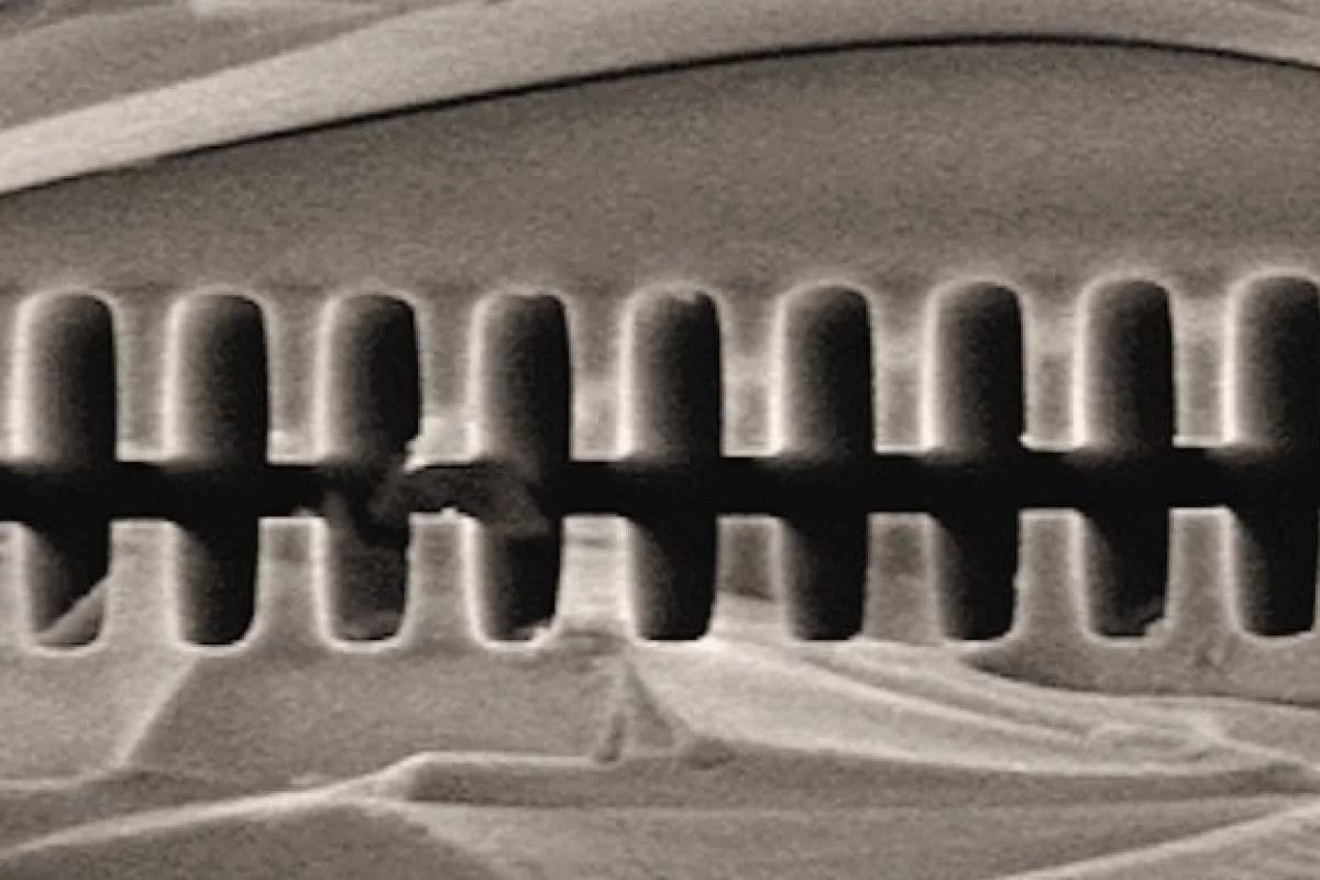
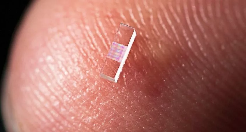
If Angus MacGyver was a particle physicist, he might face a challenge like this: Take a femtosecond laser and a fused quartz grating and make the world's most powerful particle accelerator. Despite the apparent incongruity of the resources and the goal, researchers at Stanford University and the US Department of Energy’s SLAC National Accelerator Laboratory have fabricated a proof-of-principle electron accelerator using just such equipment. In the demonstration, electrons from a 60 MeV beam saw a force of acceleration about ten times greater than possible in a conventional accelerator.
Conventional GeV and TeV-range particle accelerators are huge. The CERN Large Hadron Collider (LHC) and its companion Large Electron Positron Collider, which occupied the same 4.3 km (2.7 mile) diameter tunnel at different times, are perhaps the largest examples. The ill-fated US Superconducting Supercollider was to be about three times as large, but was cancelled when only about one-quarter of the tunnel had been dug.
Charged particles gain kinetic energy in a particle accelerator by falling through strong electric fields. The great size of very high energy accelerators results from the tendency of the accelerator structure to breakdown if these electric fields are too intense.
The practical limit on electric field intensity in conventional accelerators is about 30 megavolts per meter (MV/m), about ten times the field intensity that drives lightning strikes. In contrast, the focused light of a table-top terawatt laser can produce electric fields as large as 100 teravolts per meter – about three million times more intense, and in principle allowing a laser-driven collider to reach LHC energies in a distance of about 7 cm (3 in)!
The problem in taking advantage of the large electric fields associated with very high optical power is that the field points in opposite directions in each half of the oscillation of the light. The net result is that a charged particle receives no net acceleration unless that electric field symmetry is somehow broken. This result is known as the Lawson-Woodward theorem.
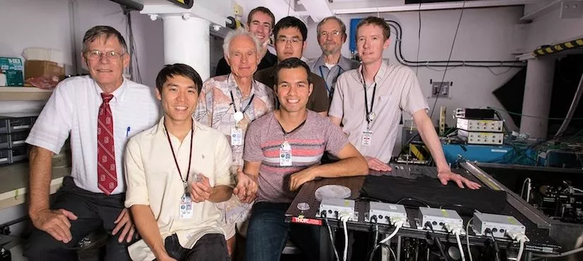
Fortunately, breaking the symmetry in oscillating electric fields associated with light is rather easy. R.L. Byer of Stanford University and Joel England of SLAC led the proof-of-principle demonstration in which laser-driven electric fields were used to accelerate a beam of electrons. They used a method called dielectric laser acceleration, in which the electric field symmetry is broken by sending the electrons through a laser-illuminated fused silica grating.
Take a pair of slabs of dielectric material, arrange them so they are separated by a gap, and then direct a plane-polarized laser beam to pass through the slabs perpendicular to the internal surfaces of the gap. The result is that an electric field is generated within and parallel to the gap. The intensity of the laser-driven electric field depends on the size of the gap, and is largest when the gap separation equals half a wavelength of the exciting laser beam.
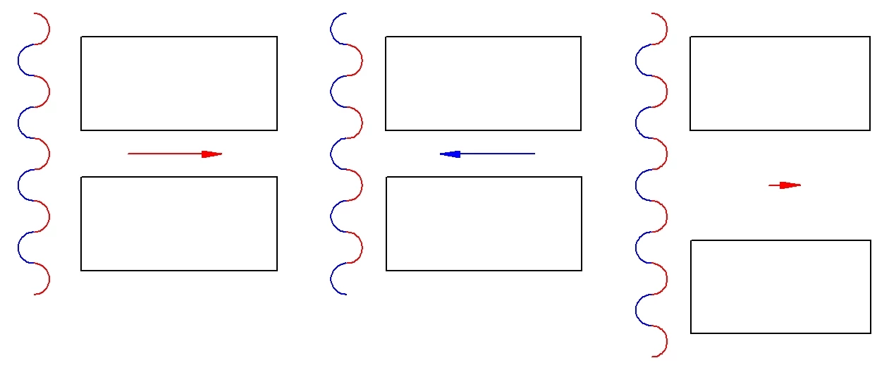
The image on the left shows a beam of laser light, which has a sideways electric field that varies between pointing right (red) and left (blue), passing through a pair of slabs with a gap equal in size to half a wavelength of the exciting laser beam. (That the index of refraction of the dielectric slabs reduces the wavelength therein has been ignored for simplicity.) As shown, only the red part of the laser beam appears in the gap, and the result is the gap has an electric field pointing to the right that is roughly equal in intensity to the average of the red half-cycle in the gap.
The center image shows the situation when the laser beam has moved on by half an oscillation. The positions of the red and blue portions of the beam have now been interchanged, with the result that the electric field in the gap is the same size as in the configuration on the left, but is reversed in direction.
The right hand image shows a similar geometry, but in which the gap is three times wider, and contains two red half-cycles and one blue half-cycle of the laser beam. What happens here is that the blue half-cycle cancels out one of the red half-cycles. The remaining source for the field in the gap is the same size, one half-cycle, as in the other configurations, but the field is spread over three times the distance. As a result, the electric field intensity in the wider gap is only about one-third that of the half-cycle wide gap.
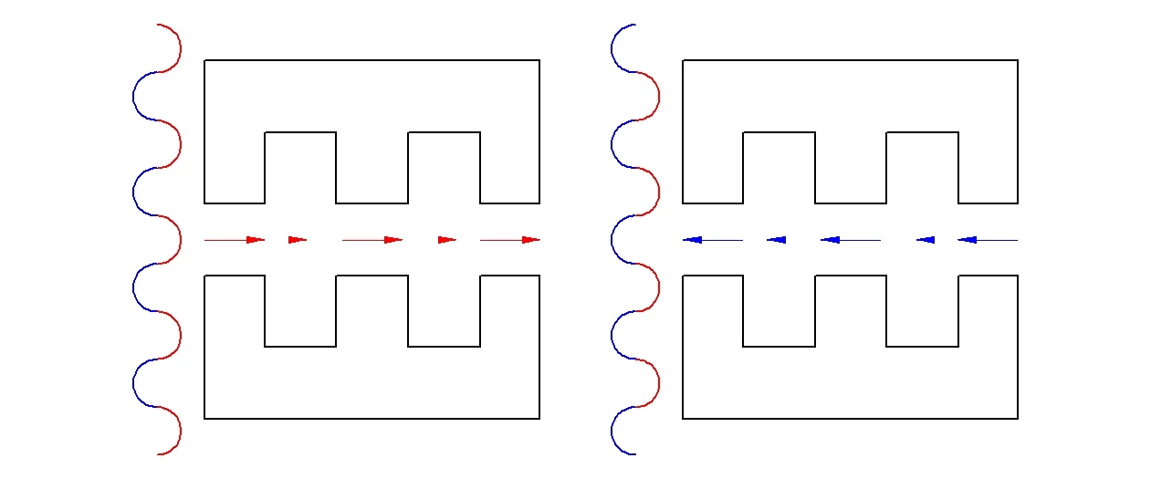
What happens if the inner surfaces of the slabs are configured into gratings? The electric fields within the gap still oscillate in direction as the laser beam passes through the dielectric slabs, but the electric field intensity is greater where the gap is narrow. This breaks the electric field symmetry, but not enough – a charged particle will still not receive any overall acceleration in the gap.
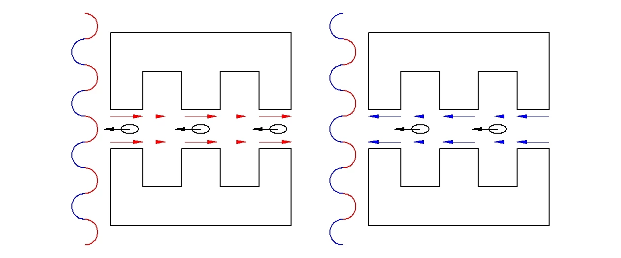
One more factor is required to obtain net acceleration of charged particles using this approach. They will have to be separated into small bunches of particles that move through the dielectric grating structure synchronized with the electric field oscillations in the grating. On the left in the figure above, small groups of electrons have been added, moving to the left. Their position here puts them in a very strong electric field, so that they are strongly accelerated to the left. (Remember, electrons have a negative charge, so are accelerated in the direction opposite to the electric field.)
The dimensions of the grating have been chosen so that when the laser beam has moved (right) by half a wavelength, thereby flipping the electric field directions. The bunches of electrons have moved far enough that they are now in the wide gap positions within the grating that have small electric fields. The electrons do feel a small acceleration to the right at this point in the cycle, but the average acceleration is strongly to the left. At this point the symmetry of the electric fields has been sufficiently broken (in space and time) that efficient laser-driven acceleration is achieved.
The Stanford-SLAC team succeeded for the first time in accelerating relativistic particles with a dielectric laser accelerator. Using an 800 nm infrared picosecond laser and a grating similar to that shown above, the total increase in kinetic energy accumulated by the electrons traversing their 0.4 mm long acceleration grating was only about 100 keV – sufficient to demonstrate the principle.
More than that, the electric field intensity in the acceleration grating was in excess of 300 MV/m, about ten times larger than seen in conventional accelerators. Another order of magnitude in field intensity, to several GV/m, is expected before difficulties with electrical breakdown of the fused quartz interfere.
There are some potentially difficult timing problems encountered in keeping the bunches of electrons in the correct location relative to the acceleration grating for continued efficient acceleration. While true, this problem was largely avoided in this proof-of-principle experiment by starting with relativistic electrons. At highly relativistic velocities, additional kinetic energy provides little increase of speed. As a result, the timing problems do not appear until the particles are accelerated to very large multiples of their original velocity.
This may seem well and good, but how can one make an accelerator which is not only capable of large energies, but also of high luminosity? In the type of accelerator studied at Stanford and SLAC, there are perhaps 40,000 electrons in each bunch. In principle, there can be one bunch of electrons for each tooth in the acceleration grating, which has a period of 400 nm. For a one picosecond laser pulse, this spacing allows nearly one million bunches of electrons to be accelerated (40 billion electrons). A laser of this class can be built to generate a train of perhaps a million pulses per second, so that the average output beam current of a DLA accelerator might be able to reach a few mA, a value comparable with the largest conventional accelerators.
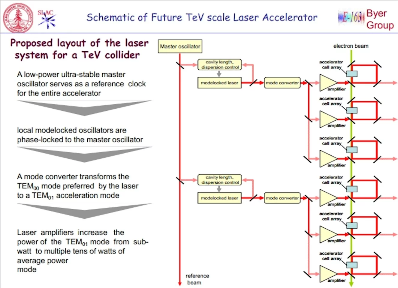
A TeV-level accelerator would have to handle timing issues properly to insure beam quality. The schematic above gives an idea of how this might be arranged. A master oscillator would link the timing of the various segments of the accelerator globally. Locally, lasers are mode-locked to the signal from the master oscillator, so that their phase relationships to the local accelerating gratings remain fixed. The laser light is converted into a form in which it will provide electric fields parallel to the path of the particles with which to accelerate them. Then the laser light is split into a number of channels, amplified so that each beam carries average powers of many watts, and is then applied to a row of accelerating gratings to accelerate the particle beam. None of this is easy, but all of it is possible.
Source: SLAC
