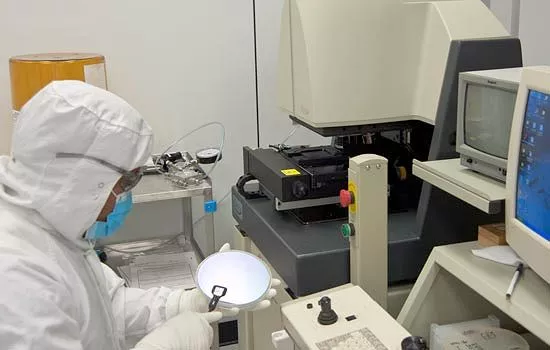
There's no doubt that mobile electronic devices have revolutionized our daily lives. A smartphone and laptop, both equipped with Bluetooth and Wi-Fi, provide mobile computing capabilities only dreamed of a decade or two ago. If only the batteries would keep up. While portable fuel cells have been proposed for a decade as a solution to the requirement for more portable power, actually making such a beast has proven commercially impractical. Now Lilliputian Systems, Inc., an MIT spinoff company, is manufacturing the Nectar, a USB recharger based on a butane fuel cell.
Burning fuel results in a good deal of heat. While this is a useful property, small amounts of heat are very difficult to efficiently convert into electrical energy. This is where fuel cells enter the picture. In the simple example shown below, a solid oxide fuel cell (SOFC) similar to that in the Nectar takes in hydrogen and oxygen, and produces electricity and water. Where does the electricity come from? Let's track the reactions taking place in the fuel cell.
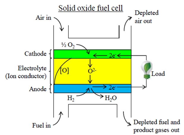
We provide the fuel cell with hydrogen gas on the anode side and oxygen (usually the oxygen in air) on the cathode side. In the cathode, the oxygen molecule splits apart and doubly charged negative oxygen ions are formed. The electrons needed to form the oxygen ions come from the anode of the cell through an electrical load. Those electrons are released in the anode by the reaction of the hydrogen fuel with the oxygen ions to form water.
The role of the electrolyte here is key as it allows the oxygen ions to easily pass between the cathode and the anode, but blocks electrons from passing. This forces these electrons to pass through the external electrical load, where their energy can do work. In the end, the properties of the electrolyte allow a fuel cell to generate electricity. A typical electrolyte for an SOFC is ceramic, a common example of which is yttrium-stabilized zirconia (YSZ).
Fuel cells typically provide less than a volt of electric potential. In the basic reaction for an H2O2 fuel cell, an oxygen ion, a hydrogen molecule, and two electrons react to form a molecule of water. The overall energy from burning a single molecule of hydrogen to form water divided by the charge of a pair of electrons is the theoretical maximum voltage of the fuel cell, which is about 1.23 eV in this case. However, in practice and under load the actual voltage is 0.7 to 0.8 V owing to a number of inefficiencies dwelling within a practical fuel cell.

In developing the Nectar, the team at Lilliputian Systems decided to use the highest energy density fuels, reaction conditions that give the highest possible system efficiency, and to make a fuel cell of large energy density, so that the Nectar beats the performance of a battery in the real world. They chose butane as a fuel, a SOFC design, and to minimize system size by using MEMS manufacturing techniques. None of these selections lead toward simple engineering problems.
Butane was chosen for its strong safety record as well as its very large energy density (about 7,400 Wh/liter when burned with about 65 liters of air). As butane will not autoignite below 400° C (750° F), the operating temperature of a butane-fueled SOFC has to be at least 500° C (900° F) and can be as large as 1,000° C (1,800° F). Maintaining such temperatures in a miniaturized low-power fuel cell requires careful thermal design and novel approaches to insulation. Uncontrolled, just the radiation losses from the Nectar fuel cell would be in excess of 200 W, which is a bit of a problem for a fuel cell with an electric power output of 2 to 3 W.
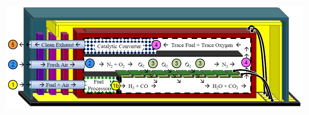
The cross-section of the Nectar MEMS fuel cell above gives a bit better idea of the way it functions. Fresh air is pumped into port 2 to provide the fuel cell with a source of oxygen. A mixture of air and butane is pumped into port 1, where it goes into a miniaturized fuel reformer. There, the fuel mixture is partially oxidized to convert the mixture into hydrogen gas and carbon monoxide. In area 3, the fuel and oxidizer react across the YSZ cell membrane, providing electrical power output, water, and carbon dioxide. Finally, the exhaust still has a bit of fuel mixed in, so it is sent through a catalytic converter 4 before being released to the atmosphere.
All of this occurs on a silicon die about 21 mm (0.8 in) on a side, which is piled up with many layers of fuel cells to achieve the desired operating voltages and power density. To add to the problems, extraordinarly effective thermal insulation is required to obtain a few watts of electrical output without burning ridiculous amounts of fuel just to maintain the 600 to 800° C operating temperature of the fuel cells. If conventional insulation were used, several hundred watts of thermal energy could easily be required simply to heat the fuel cell.
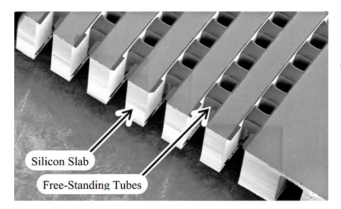
This is where MEMS processing techniques enter in. The fuel cell passages and tubes are built on a silicon slab, but are made of very thin free-standing silicon nitride walls to reduce the physical heat conduction within the fuel cell. The spaces outside the fuel and oxygen paths are also held at vacuum to remove thermal conduction and convection from the air which would otherwise fill those spaces. Finally, a series of highly reflective surfaces dramatically reduces the loss of thermal energy to thermal radiation. Tests of the completed structure show that the loss of thermal energy from the fuel cell is tolerable, about three watts at 600° C, rising to about seven watts at 800° C.
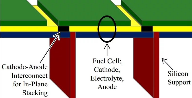
One of the consequences of building the fuel cell as a MEMS structure is that its foundation is silicon, whose thermal expansion is not well matched with that of YSZ. Between room temperature and operating temperature, as much as one GPa (10,000 atmospheres) of stress can appear in the YSZ membrane, which is well above its elastic limits. At the same time, if the membrane cracks in response to the stress, the fuel and oxygen can react without forcing oxygen ions across the membrane, leading quickly to a non-functioning fuel cell.
As there seemed to be no modification of the manufacturing procedure that would prevent the membrane from cracking, Lilliputian took the approach of forcing the cracks to occur in harmless locations. The membrane only cracks in locations where the cracks are presealed by other materials. The membrane remains intact in the active fuel cell regions.
A fuel cell system also requires pumps for the fuel and air streams. The Nectar supplies the need by having a single air pump that provides both the oxygen supply and the air to be mixed with the fuel. The fuel is added to that portion of the pumped air through a device that is in essence a tiny carburetor. A temperature controller measures and maintains a constant temperature by varying the rate at which fuel is introduced to the fuel cell. Various electronics to collect and regulate the electrical power output are also included, which is a necessity if the unit is to be USB compatible.
All-in-all, the Nectar is a remarkable engineering achievement. Squeezing a complete computer-compatible fuel cell power supply within the nine cubic inches (147 cc) and seven ounces (198 g) of the Nectar unit required years of development and more than US$100M of funding. The resulting system will provide a recharge at a rate of about 2.5 W, with the voltage adjusted to match your battery by an internal DC-DC converter. One container of butane will provide a total of 55 Wh of electrical energy, which is enough to recharge most mobile phones about ten times, or a laptop battery once.
The remaining question, however, is if there is a place in the market for the Nectar unit, given its initial price of US$300, with each 55 Wh butane canister costing $10? According to Lilliputian's early market research, there would be a large number of buyers at a price point of $100, but only about five percent of potential purchasers would consider the unit at $300. Will this noteworthy new product survive, or will it founder on the shoals of unreasonable price? Only time will tell.
Source: Lilliputian Systems, Inc.

